3D printing is a rabbit hole. In one hand, it is an extremely flexible tool. The possibility to quickly go from a drawing, from an idea to a physical object, at an affordable price, is simply amazing. In other hand, depending on the person (if one likes to thinker), it becomes a hobby in itself.
When engaging a new tool, a new hobby I usually start with a cheaper tool, and then decide if I should pursue the hobby further should I outgrow the tool. This is where I am at with my ender 3 V2.
Trophies under post delivery inspection after unpacking.
Context : Revival of the Inercia Association
As far as I am concerned, Jeenio’s initiative of reviving Inercia association, and thus ensuring continuation of Inercia Demoparty, was a very important milestone on the portuguese demoscene.
And, as such, I wanted to find a way to contribute to Inércia demoparty. One of the organizers, psenough, asked for someone to print the trophies for the compos , and it seemed to be a good synergy between what I like to do and what contribution would be useful to the party.
How it began
Work on the trophies for the Inercia Demoparty 2022 began on April of 2022, using harvestpt Inercia designs as basis. I was given free reign on the design and materials to use.
The community onscenePT discord was consulted and regularly informed of the progress of the work on the trophy design as it happened.
Designs
The major goal was to have a custom designed trophy – I did not want to just get a trophy from thingiverse and stick a inercia logo on it.
The trophies were designed on blender, sliced on Cura and printed on a Ender 3V2.
The list is not complete. I´ve decided to stick to libyaul. On windows it was simple to setup, examples could be easy compiled out of the box, and it has a helpful and active community on discord , where the author of libyaul is also part of.
Hello World
Makefile
The make file was just a modified makefile already available from the exemples provided with libyaul.
Code
#include <yaul.h>

#include <stdio.h>
#include <stdlib.h>

void main(void)
{
    //init the subsystem to print debug text to the screen
    dbgio_dev_default_init(DBGIO_DEV_VDP2_SIMPLE);
    dbgio_dev_font_load();
    dbgio_dev_font_load_wait();

    //enable vdp2
    vdp2_tvmd_display_set();

    while(1)
    {
        dbgio_printf("\x1b[H\x1b[2J");  // clears the screen
        dbgio_printf("Hello World\n");  // actual text
        dbgio_flush();                  // flush
        vdp_sync();                     // required at the end of each frame
    }
}
Light meter with a FTDI USB – Serial Interface for sw development
I love analogue photography, even more when it’s with fully mechanical medium format cameras, such as the Flexaret Automat VII, and the Hasselblad 500c.
However, where are some situations where the correct exposure is difficult to determine. On such cases, one could use a second camera for TTL metering (such as DSLR), a phone app…or a light meter.
On my location, an new sektronick light meter price varies from 109 € to 600 € depending on the model. On ebay you could get an used, cheaper , vintage light meter, but your mileage might vary.
So since the price and availability of light meters were not to my liking, I’ve decided to build my own from scratch, based on an arduino board, with some help of Pedro Virtebo, at Maquinas de Outros Tempos.
Bear in mind this is not the first or last time anyone has done something similar, a simple google search show a ton of similar projects, with different levels of polish. But just implementing these would not give me enough understanding of how a light meter works.
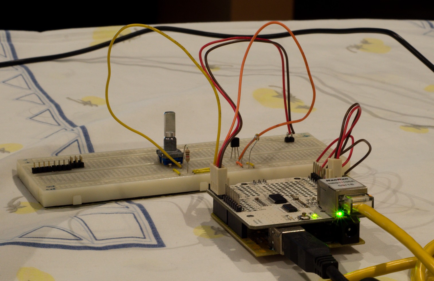
The initial sensor module was done with an Arduino + DS18B20 sensor and a ENC28J60 ethernet chip. It was pretty fast to build a prototype that would send data via ethernet to a server running a LAMP stack.
However, since I want to have sensors trough out the house (including the exterior), it became a problem since I’m unable to pass an Ethernet cable everywhere I might need a sensor module installed.
The cheapest to add wifi capabilities to an arduino based system would be to add an ESP8622 wifi module :
They are low priced – around 1,7€ a piece on ebay.
Answer to AT commands via serial communication (thus an arduino board could simply send AT commands to the module with the data).
But upon more reading, it was also noted that the ESP8266 could be used as a stand alone module, without the arduino hardware. This helps drive the cost and assembly complexity of each module down further. A major plus was the fact that the arduino IDE can be used with the ESP8266, work with most libraries already included, without changes to software development workflow.
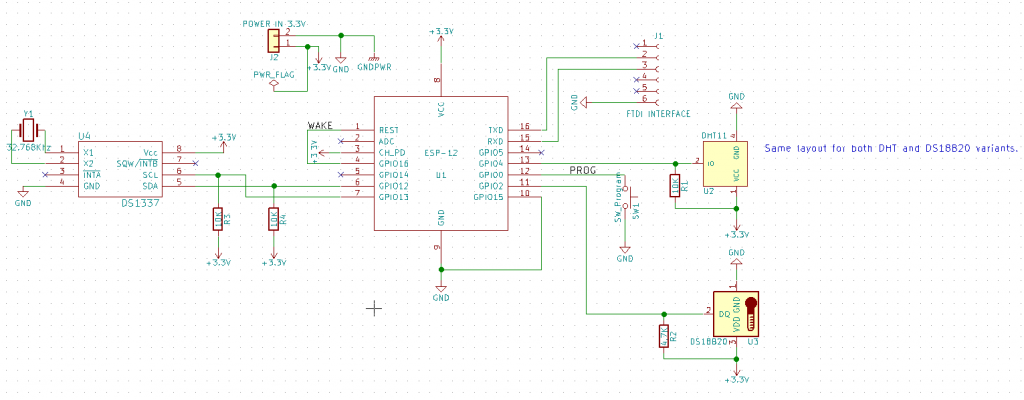
Sensor Module Schematics for version 1.0. Notice the few component count.
And since the ESP8266 supports I2C and 1 wire data buses, any sensor supporting those protocols can be added to a ESP8266 module.
Sensor module variants
ESP8266 based sensor Modules – PCB version 1 and Breadboard prototypes during code development
A total of 3 variants of the ESP8266 based sensor module, as of 17th February, were built:
A module only using a temperature sensor (the DS18B20), with no RTC on board. Exists in breadboard form only and it is currently in use.
A module using both a DHT22 humidity and temperature sensor, and also a DS18B20 sensor. Also without RTC support. Module was disassembled and parts used on the PCB version 1.0.
A module using a DHT22 humidity and temperature sensor, with a DS1337 RTC, as used on my Nixie Clock. This version was built on a PCB designed in KICAD, and it is currently in use.
Changes to the Home Monitoring System Architecture
Almost a year later, and a working prototype, the development of the monitoring system had reached a standstill, mostly due to the lack of time :
On the sensor side , the Arduino + ENC28J60 + DS18B20 combo works, although it is dependent on the availability of a network cable. But the hardware is functional.
On the server side , the development of a backend and frontend with the flexibility required (multiple sensor support, dashboard with user selected time intervals, etc) was starting to take too much time.
Sensor : Arduino + ENC28J60 + DS18B20, Server Side : LAMP stack, chart done with chart.js
So I was faced with a decision regarding the server side of the system:
Fully development of a frontend and backend , using a LAMP stack and bootstrap templates. This would take time that I simply don’t have, and the project would probably still be stalled.
Or find a solution that would require less effort. And this was only an option when I was introduced to Elasticsearch + kibana stack.
On the hardware side, I had some ESP8622 (ESP-12) modules to try out.
ESP8622 Sensor Module prototype with a DS18B20 temperature sensor
Current Status
Server Side changes
The server side of the Monitoring system was the one that was the most time consuming.
One of the major changes was the replacement of the LAMP stack for elasticsearch and kibana for data storage and visualization respectively. This removed the need to write a backend and a frontend from scratch. The time that would be spent on writing the back and front ends was spent on the sensor module development (both hardware and software).
Elasticsearch, according to the authors:
” Elasticsearch is an open source distributed, RESTful search and analytics engine capable of solving a growing number of use cases.”
With elasticsearch, the sensor modules sends data in json , instead of sending the data via http get to a php script with the previous Monit System architecture.
And a dashboard with visualizations of the data can be done in minutes.
KIbana Dashboard
Hardware changes
Although the arduino + enc28J60 sensor module was not entirely abandoned, hardware development focus was oriented on the ESP8622 based modules.
The ESP8622 have some interesting advantages over the arduino + ENC28J60 combination :
The ESP8622 can be sourced from around 1,7 € a piece (ESP-12) (and it replaces the arduino board and the ENC28J60 in one package)
It can be used with the Arduino IDE , and use most of its libraries (no need to learn a new SDK and new tools).
No additional network hardware required, since the ESP module is a wifi module first and foremost (DHCP, WPA2 supported out of the box), and thus I could place the sensor module anywhere as long as there is wifi coverage, including the exterior of the house.
Less parts per module, since the ESP8622 has an ARM CPU besides the WiFi capabilities : besides the module itself, only the sensor, a RTC (if needed) and some passive components are needed.
However the usage of the bare modules are not as “plug and play” as with arduino boards – additional hardware and wiring required . This is not an issue since the final goal is to have a custom made PCB for the sensor module.
For a long , long time I wanted to have a system to monitor, and perform data collection, on my home.
A modular system where I could gather data from indoor and outdoor temperatures to local power consumption.
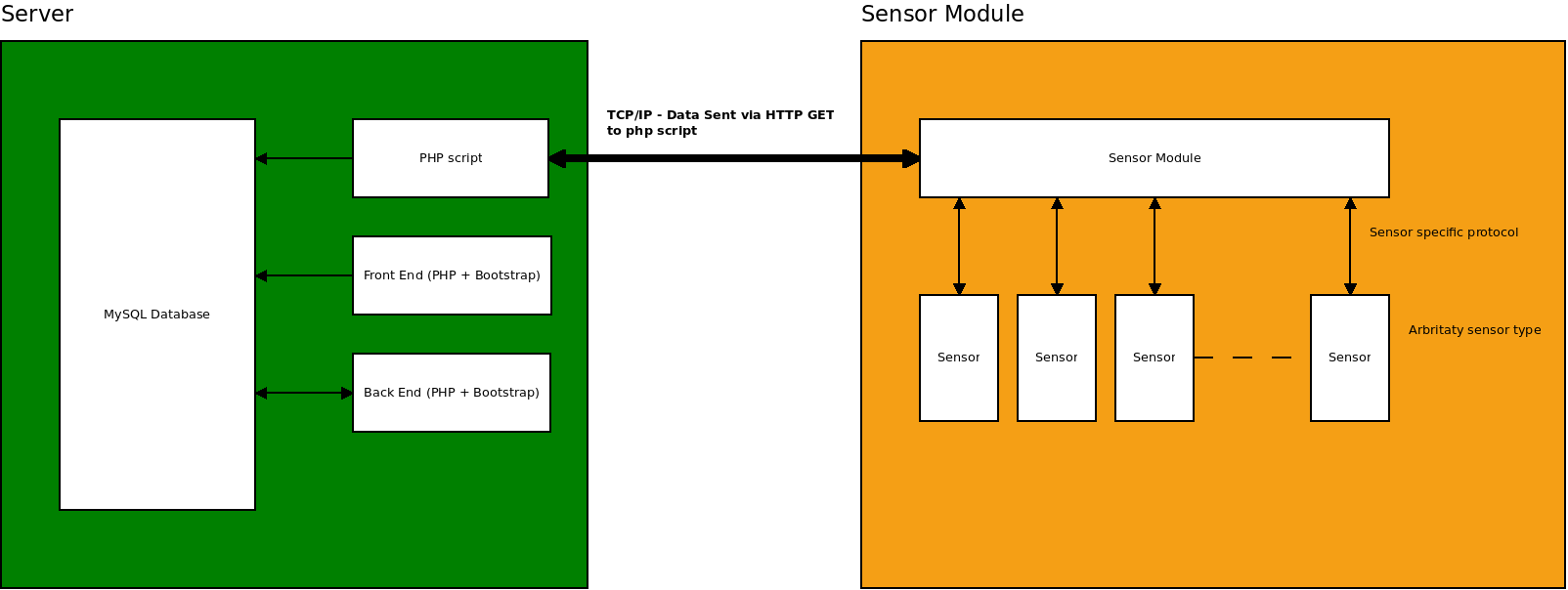
CasaMonit Initial Architecture proposal
The system is meant to be designed in such manner that the server side is fully abstracted from the sensor module side, more sensors modules may be implemented on different hardware platforms. There can be as many sensor modules as required, connected on a single Ethernet network.